INTRODUCTION:
Circuits consisting of just one battery and one load resistance are very simple to analyze, but they are not often found in practical applications. Usually, we find circuits where more than two components are connected together.
There are two basic ways in which to connect more than two circuit components: series and parallel.
series circuit:
Nodes and Current Flow
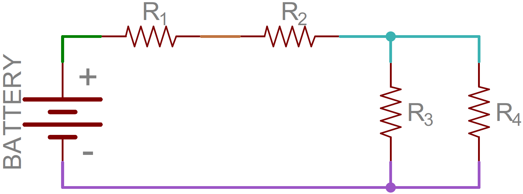
Before we get too deep into this, we need to mention what a node is. It’s nothing fancy, just the electrical junction between two or more components. When a circuit is modeled on a schematic, the nodes are the wires between components.
That’s half the battle towards understanding the difference between series and parallel. We also need to understand how current flows through a circuit. Current flows from a high voltage to a lower voltage in a circuit. Some amount of current will flow through every path it can take to get to the point of lowest voltage (usually called ground). Using the above circuit as an example, here’s how current would flow as it runs from the battery’s positive terminal to the negative:
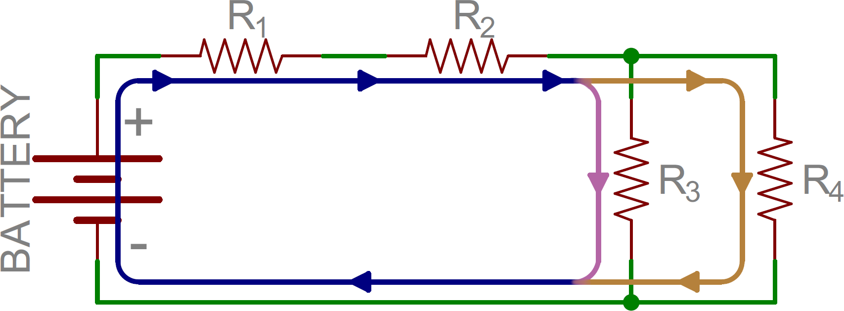
Current (indicated by the blue, orange, and pink lines) flowing through the same example circuit as above. Different currents are indicated by different colors.
Notice that in some nodes (like between R1 and R2) the current is the same going in as at is coming out. At other nodes (specifically the three-way junction between R2, R3, and R4) the main (blue) current splits into two different ones. That’s the key difference between series and parallel!
Series Circuits Defined
Two components are in series if they share a common node and if the same current flows through them. Here’s an example circuit with three series resistors:
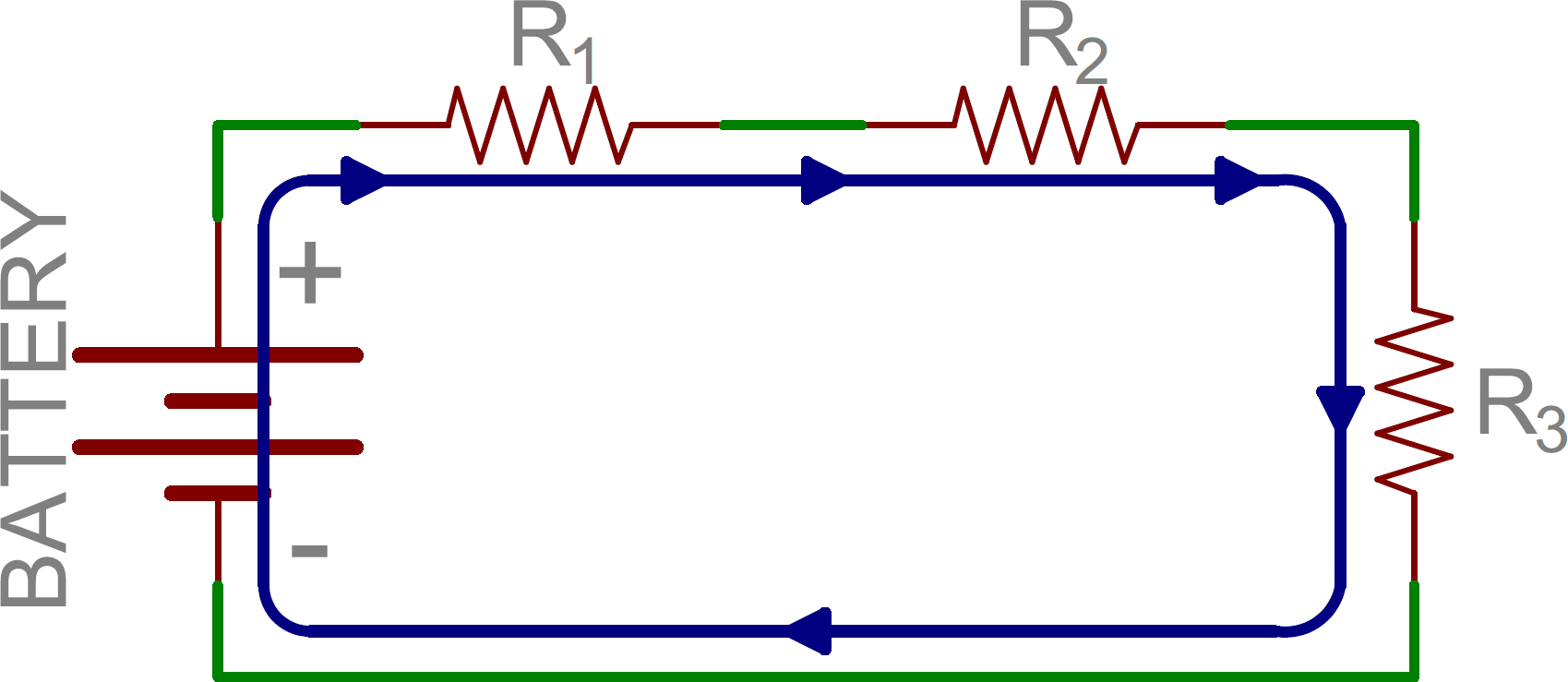
There’s only one way for the current to flow in the above circuit. Starting from the positive terminal of the battery, current flow will first encounter R1. From there the current will flow straight to R2, then to R3, and finally back to the negative terminal of the battery. Note that there is only one path for current to follow. These components are in series.
Parallel Circuits
Parallel Circuits Defined
If components share two common nodes, they are in parallel. Here’s an example schematic of three resistors in parallel with a battery:
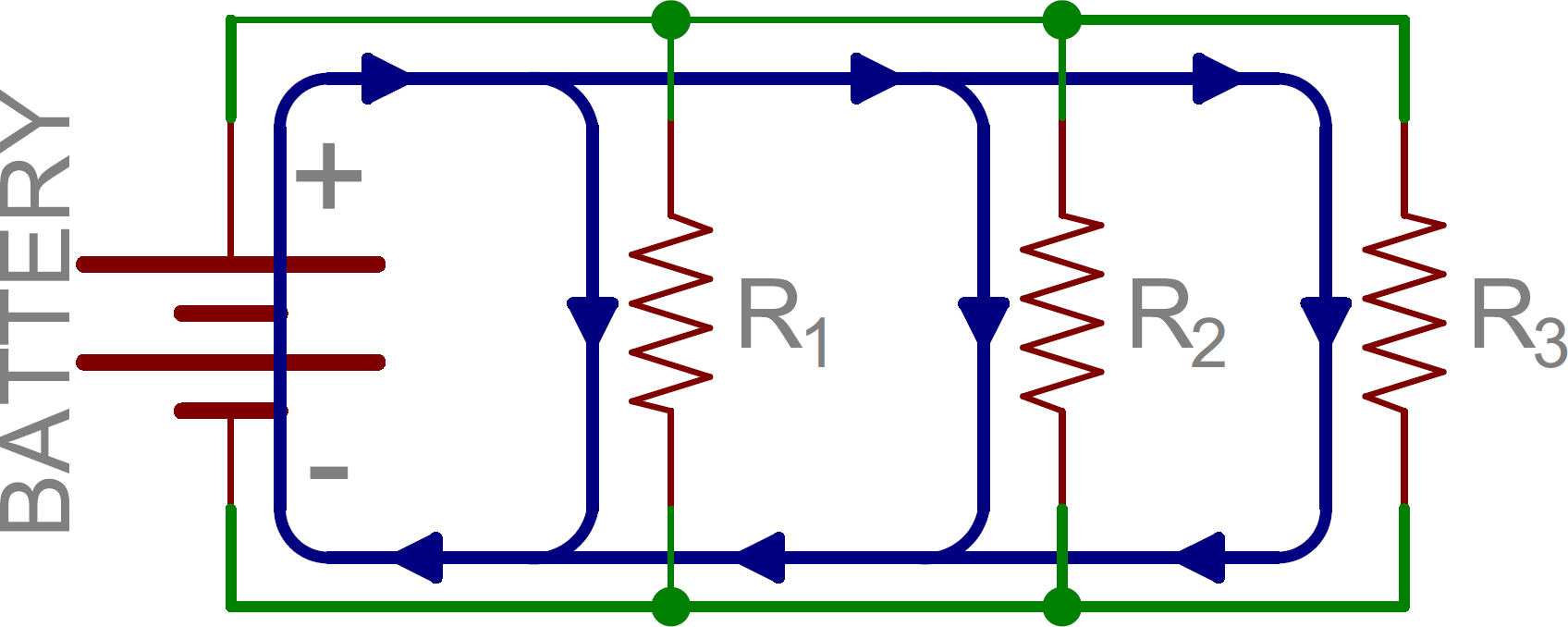
From the positive battery terminal, current flows to R1… and R2, and R3. The node that connects the battery to R1 is also connected to the other resistors. The other ends of these resistors are similarly tied together, and then tied back to the negative terminal of the battery. There are three distinct paths that current can take before returning to the battery, and the associated resistors are said to be in parallel.
Where series components all have equal currents running through them, parallel components all have the same voltage drop across them – series:current::parallel:voltage.
Series and Parallel Circuits Working Together
From there we can mix and match. In the next picture, we again see three resistors and a battery. From the positive battery terminal, current first encounters R1. But, at the other side of R1 the node splits, and current can go to both R2 and R3. The current paths through R2 and R3 are then tied together again, and current goes back to the negative terminal of the battery.
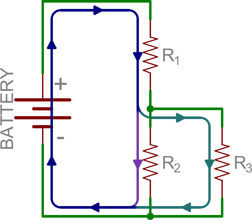
In this example, R2 and R3 are in parallel with each other, and R1 is in series with the parallel combination of R2 and R3.
Calculating Equivalent Resistances in Series Circuits
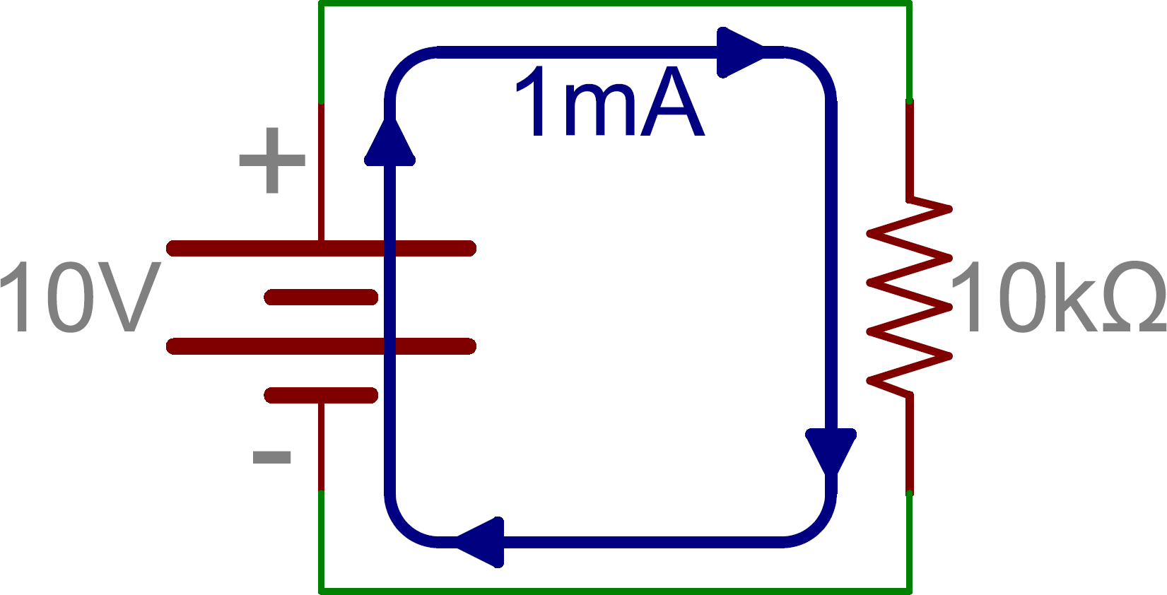
Here’s some information that may be of some more practical use to you. When we put resistors together like this, in series and parallel, we change the way current flows through them. For example, if we have a 10V supply across a 10kΩ resistor, Ohm’s law says we’ve got 1mA of current flowing.
If we then put another 10kΩ resistor in series with the first and leave the supply unchanged, we’ve cut the current in half because the resistance is doubled.
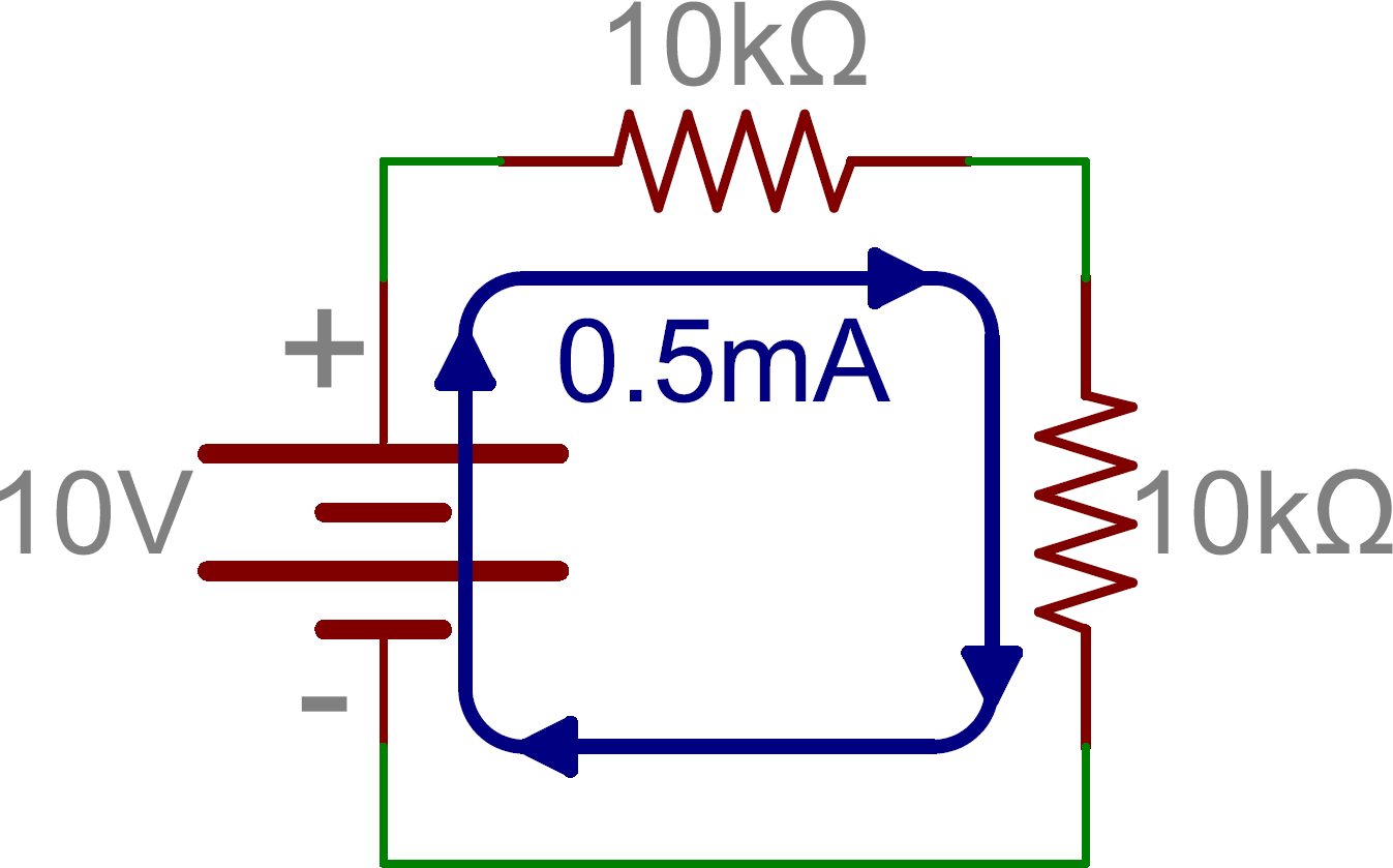
In other words, there’s still only one path for current to take and we just made it even harder for current to flow. How much harder? 10kΩ + 10kΩ = 20kΩ. And, that’s how we calculate resistors in series – just add their values.
To put this equation more generally: the total resistance of N – some arbitrary number of – resistors is their total sum.
Calculating Equivalent Resistances in Parallel Circuits
What about parallel resistors? That’s a bit more complicated, but not by much. Consider the last example where we started with a 10V supply and a 10kΩ resistor, but this time we add another 10kΩ in parallel instead of series. Now there are two paths for current to take. Since the supply voltage didn’t change, Ohm’s Law says the first resistor is still going to draw 1mA. But, so is the second resistor, and we now have a total of 2mA coming from the supply, doubling the original 1mA. This implies that we’ve cut the total resistance in half.
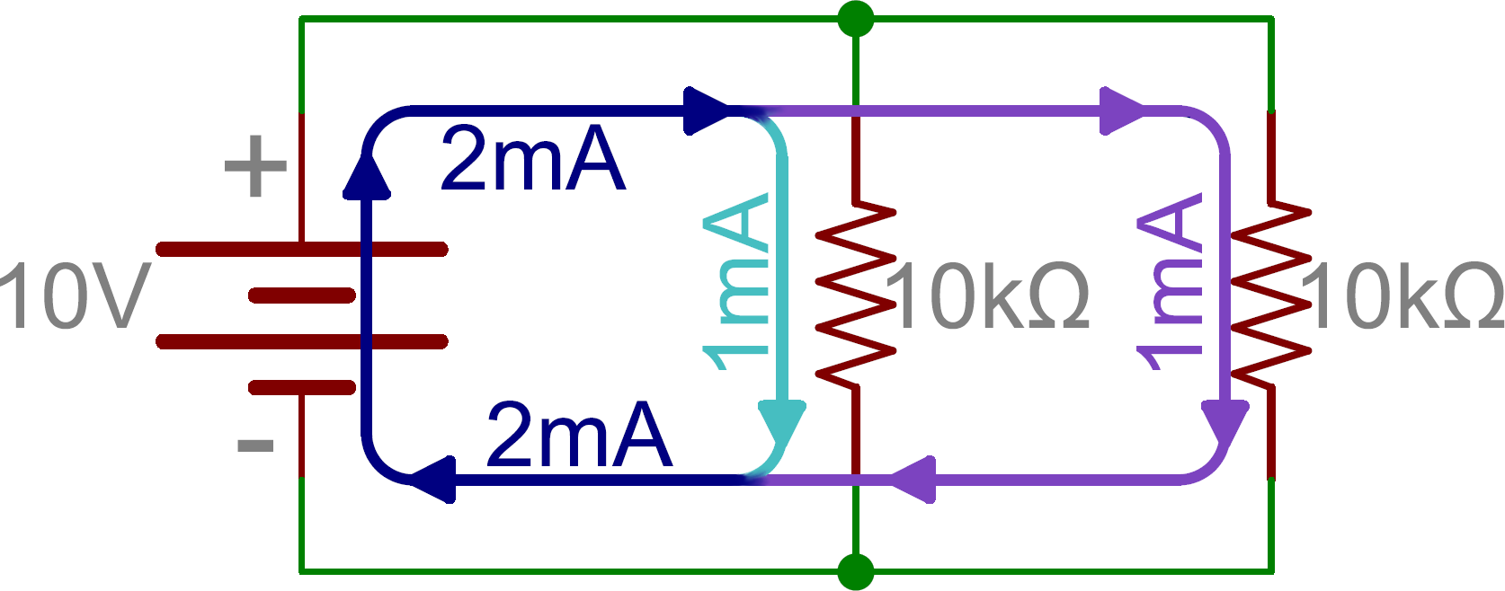
While we can say that 10kΩ || 10kΩ = 5kΩ (“||” roughly translates to “in parallel with”), we’re not always going to have 2 identical resistors. What then?
The equation for adding an arbitrary number of resistors in parallel is:
If reciprocals aren’t your thing, we can also use a method called “product over sum” when we have two resistors in parallel:
However, this method is only good for two resistors in one calculation. We can combine more than 2 resistors with this method by taking the result of R1 || R2 and calculating that value in parallel with a third resistor (again as product over sum), but the reciprocal method may be less work.
Series and Parallel Capacitors
Combining capacitors is just like combining resistors…only the opposite. As odd as that sounds, it’s absolutely true. Why would this be?
A capacitor is just two plates spaced very close together, and it’s basic function is to hold a whole bunch of electrons. The greater the value of capacitance, the more electrons it can hold. If the size of the plates is increased, the capacitance goes up because there’s physically more space for electrons to hang out. And if the plates are moved farther apart, the capacitance goes down, because the electric field strength between them goes down as the distance goes up.
Now let’s say we’ve got two 10µF capacitors wired together in series, and let’s say they’re both charged up and ready discharge into the friend sitting next to you.
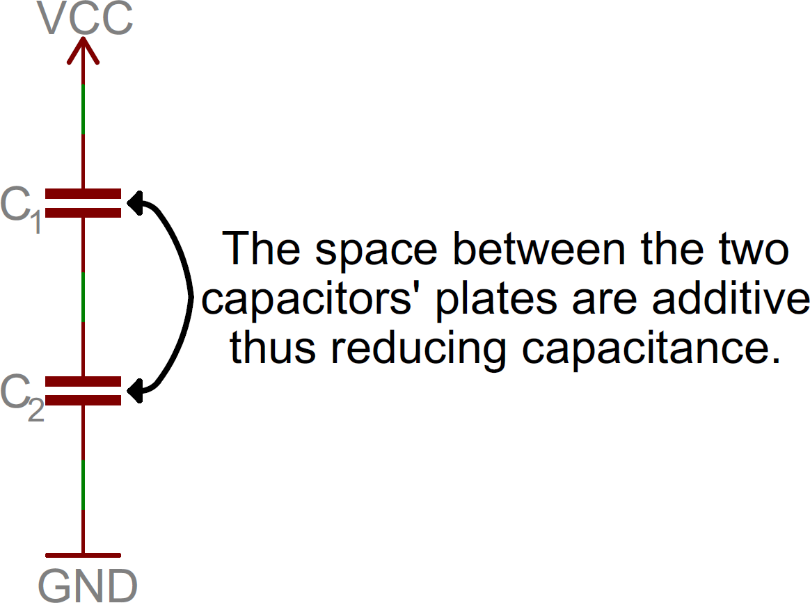
Remember that in a series circuit there’s only one path for current to flow. It follows that the number of electrons that are discharging from the cap on the bottom is going to be the same number of electrons coming out of the cap on the top. So the capacitance hasn’t increased, has it?
In fact, it’s even worse than that. By placing the capacitors in series, we’ve effectively spaced the plates farther apart because the spacing between the plates of the two capacitors adds together. So we don’t have 20µF, or even 10µF. We’ve got 5µF. The upshot of this is that we add series capacitor values the same way we add parallel resistor values. Both the product-over-sum and reciprocal methods are valid for adding capacitors in series.

may seem that there’s no point to adding capacitors in series. But it should be pointed out that one thing we did get is twice as much voltage (or voltage ratings). Just like batteries, when we put capacitors together in series the voltages add up.
Adding capacitors in parallel is like adding resistors in series: the values just add up, no tricks. Why is this? Putting them in parallel effectively increases the size of the plates without increasing the distance between them. More area equals more capacitance. Simple.



No comments:
Post a Comment