Power Factor

Introduction:

In electrical engineering, the power factor of an AC electrical power system is defined as the ratio of the real power flowing to the load to the apparent power in the circuit, and is a dimensionless number in the closed interval of −1 to 1.


Definition and calculation:

AC power flow has two components:

  • Real power or active power (), expressed in watts (W)

  • Reactive power (), usually expressed in reactive volt-amperes (var)

These are combined to the Complex power () expressed volt-amperes (VA). The magnitude of the Complex power is the Apparent power (), also expressed volt-amperes (VA).

The VA and var are non-SI units mathematically identical to the Watt, but are used in engineering practice instead of the Watt in order to state what quantity is being expressed. The SI explicitly disallows using units for this purpose or as the only source of information about a physical quantity as used.

The power factor is defined as the ratio of real power to apparent power. As power is transferred along a transmission line, it does not consist purely of real power that can do work once transferred to the load, but rather consists of a combination of real and reactive power, called apparent power. The power factor describes the amount of real power transmitted along a transmission line relative to the total apparent power flowing in the line.

The Power Triangle:
Power triangle diagram.jpg

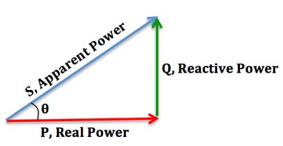
We can relate the various components of AC power by using the power triangle. Real power extends horizontally in the î direction as it represents a purely real component of AC power. Reactive power extends in the direction of ĵ as it represents a purely imaginary component of AC power. Complex power (and its magnitude, Apparent power) represents a combination of both real and reactive power, and therefore can be calculated by using the vector sum of these two components. We can conclude that the mathematical relationship between these components is:


Increasing the Power Factor:

Increased power factor.jpg

As the power factor (i.e. cos θ) increases, the ratio of real power to apparent power (which = cos θ), increases and approaches unity (1), while the angle θ decreases and the reactive power decreases. [As cos θ → 1, its maximum possible value, θ → 0 and so Q → 0, as the load becomes less reactive and more purely resistive].

Decreasing the Power Factor:

Decreased power factor.jpg

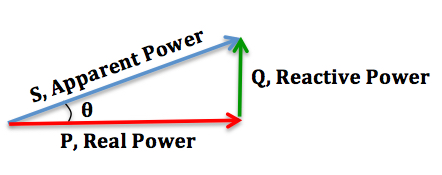
As the power factor decreases, the ratio of real power to apparent power also decreases, as the angle θ increases and reactive power increases.

Lagging and Leading Power Factors:

In addition, there is also a difference between a lagging and leading power factor. The terms refer to whether the phase of the current is leading or lagging the phase of the voltage. A lagging power factor signifies that the load is inductive, as the load will “consume” reactive power, and therefore the reactive component is positive as reactive power travels through the circuit and is “consumed” by the inductive load. A leading power factor signifies that the load is capacitive, as the load “supplies” reactive power, and therefore the reactive component is negative as reactive power is being supplied to the circuit.

 
Lagging-Leading.jpg

If θ is the phase angle between the current and voltage, then the power factor is equal to the cosine of the angle, :

Since the units are consistent, the power factor is by definition a dimensionless number between −1 and 1. When power factor is equal to 0, the energy flow is entirely reactive and stored energy in the load returns to the source on each cycle. When the power factor is 1, all the energy supplied by the source is consumed by the load. Power factors are usually stated as "leading" or "lagging" to show the sign of the phase angle. Capacitive loads are leading (current leads voltage), and inductive loads are lagging (current lags voltage).

If a purely resistive load is connected to a power supply, current and voltage will change polarity in step, the power factor will be 1, and the electrical energy flows in a single direction across the network in each cycle. Inductive loads such as induction motors (any type of wound coil) consume reactive power with current waveform lagging the voltage. Capacitive loads such as capacitor banks or buried cable generate reactive power with current phase leading the voltage. Both types of loads will absorb energy during part of the AC cycle, which is stored in the device's magnetic or electric field, only to return this energy back to the source during the rest of the cycle.

For example, to get 1 kW of real power, if the power factor is unity, 1 kVA of apparent power needs to be transferred (1 kW ÷ 1 = 1 kVA). At low values of power factor, more apparent power needs to be transferred to get the same real power. To get 1 kW of real power at 0.2 power factor, 5 kVA of apparent power needs to be transferred (1 kW ÷ 0.2 = 5 kVA). This apparent power must be produced and transmitted to the load, and is subject to the losses in the production and transmission processes.

Electrical loads consuming alternating current power consume both real power and reactive power. The vector sum of real and reactive power is the apparent power. The presence of reactive power causes the real power to be less than the apparent power, and so, the electric load has a power factor of less than 1.

A negative power factor (0 to -1) can result from returning power to the source, such as in the case of a building fitted with solar panels when surplus power is fed back into the supply.


Next topic: Power factor correction


No comments:

Post a Comment

Recent posts

professional engineer

would you like to develop your carrier into electrical fields then sign into www.electricalmastar.com www.electricalmastar.com

Popular posts